
 For CASIO Cable Do-It-Yourself Instructions (v.2, 01/1998)
1. Component List
|
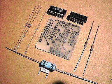
Please check first if you have all necessary electronic parts (see photo to the left):
- Resistor 4k7 (Color-Rings: yellow-magenta-red)
- Resistor 68k (Color-Rings: blue-grey-orange)
- El. Capacitor 10uF/25V
- Capacitor 100nF
- Diode 1N4148 (3 pcs.)
- Zener Diode ZD 5v1
- IC 4049
- IC 75C188 (CMOS version of MC1488)
|
|
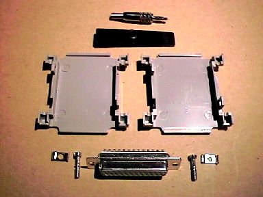
You'll also need the following mechanical parts (see photo to the left):
- Diode Cable 2x0.1mm Length in m 1,25
- Back Plane with Rubber Sleeve (to protect the cable)
- 2,5mm Stereo Jack (attention: this part must be very slim to fit CASIO)
- SubD 25pin Socket
- SubD 25pin Cover (Box) with screws
- Printed Circuit Board (PCB) (on the previous photo), see further for exact PCB artwork
(Dimensions: 36 x 39 mm), and component layout.
|
|
|
|
Here is a PCB Artwork, shown non-inverted!
(pay attention on two text fields, showing 01/98 and CASIO Link v2).
If you save this image, you can process it with virtualy any graphic software,
and print it on some good laser printer (to my experience, Canon's have a good printing machine).
By using a clear photocopy thermal foil instead of paper, you can directly obtain artwork for photo-method!
|
On this Component Layout you can see exact position of every component.
A light blue (cyan) lines you can see on this picture are in fact coper tracks on the solder side (on this view:
back side) of the Printed Circuit Board (PCB). These are shown here only for better orientation!
Please note that MC1488 is the same as 75C188 (must be CMOS-type in order to lower power consumption of the whole circuit).
|
2. Assembling Printed Circuit Board
Please clean the solder side of the PCB before soldering.
At best, use a piece of very fine brush paper to polish copper tracks.
First solder the smallest components, resistors and diodes. Pay attention on diodes polarity!
Now you can solder the two IC's. Again, pay attention on the position of pin 1!
Finally, you can solder two capacitors, again paying attention on the polarity of electrolytic capacitor.
3. Assembling PCB with DB25 Connector
To assemble these two parts, just push the PCB between two rows of pins on the DB25 connector!
The solder side of the PCB should face the pins 1-13, pins 14-25 should be on the component side.
Solder the pins directly to the PCB, beginning with pin 2.
You should also solder one wire link, just near the DB25 pins.
Please, refer to Component Layout above for exact position,
it's the horizontal one you should solder first! Solder it on the component side of the PCB!
After soldering it, use another short wire link to connect the first one to pin 20 of DB25
(not pin 7, you are looking on the component side of the PCB!).
This is the vertical wire link on the Component Layout as shown above.
Please, solder this one again on the component side of the PCB!
4. Assembling Cable With Metal Connector
|
First solder metal connector to the cable. This is the critical part of your project because of its small size.
The metal connector itself has a metal case (S), middle contact (R) and a tip contact (T).
Solder first the screening wires of the cable to S (a kind of small flag connected to S with cable fastener).
Now solder the corresponding wires from the cable to tip and middle contact.
Check that everything is very slick, with very little solder.
Now you can close the case of the metal connector. Check with multimeter for shortcuts!
Are you sure that no wire (red or white) from the cable touches the case?
If so, you will have a short contact - your cable won't function!
|
5. Assembling Cable With PCB
First put the other end of the cable through rubber sleeve on the backplane.
Using Component Layout photo above, solder now the screening of the cable to one
of the points marked with S, than corresponding wires to points R and T.
If you wrap the screening around the cable one or two times before soldering, you should achieve
rather good mechanical connection also. Check your handwork again please! Check again with multimeter for shortcuts
and if the tip (T) contact of the plug really connects to T point on the PCB and the same for ring (R) contact.
6. Assembling The Case
Just put your PCB in the middle of two box halves, put two small screws in place and press the halves
together - your
cable is complete! Of course, you can use a drop of Loctite SuperAttak (or similar)
to fasten the backplane in place. The parts of the case can also be color-sprayed before assembling,
if you like some special effects.
Now you can proceed to CASIO Cable Connecting & Debuging Instructions
Do you also want to try to build your InterCASIO Cable yourself? I've prepared here complete
Do-It-Yourself Istructions for home constructors.
Are you sick trying to assemble that damn cable yourself? Make your life easy: order one fully assembled
and tested cable
by using my special Electronic Order Form!

